White Paper: SDV Applications for Automotive ECUs
Posted: October 5, 2026

Achieving Cybersecurity and Functional Safety Compliance Through a Holistic Software Product Lifecycle Management
Abstract—Software defined vehicles (SDVs) represent a paradigm shift in the development of automotive systems as functional innovation shifts from hardware domain to software. As original equipment manufacturers (OEMs) assume an increasing role in onboard and offboard software development, traditional processes and software development methods are no longer adequate to deal with the increasing software complexities and compliance requirements. It is also noted that software development processes are often disconnected from hardware which makes it difficult to maintain consistency and quality, while ensuring compliance with international regulations.
This paper proposes a comprehensive Software Product Lifecycle Management (S-PLM) methodology to address system design, functional safety and cybersecurity challenges in SDV development. The paper illustrates how integrated lifecycle management and traceability can be used to offer continuous compliance throughout the entire development, production, and operation lifecycle, using well-defined automotive standards including AUTOSAR, functional safety (ISO 26262), cybersecurity (ISO/SAE 21434), and ASPICE (Automotive Software Process Improvement and Capability Determination). A case study of an immobilizer manager is included to demonstrate how the proposed S-PLM method can be applied to a multi-domain automotive scenario.
Keywords—Software Defined Vehicles (SDVs); Cybersecurity (ISO/SAE 21434); Functional Safety (ISO 26262); Software Product Lifecycle Management (S-PLM); Automotive Software Process Improvement and Capability Determination (ASPICE); AUTOSAR.
I. Introduction
The automotive industry is experiencing a major transformation due to the emergence of SDVs. This has changed how car manufacturers and their customers interact with vehicle functionality. Traditional methods of manufacturing vehicles have always relied upon mechanical and electrical systems to control various functions of the vehicle. With software development now comprising over 90% of the innovation in the automotive industry, software-centric development methodologies are becoming more common. SDVs will enable auto makers to use the best software and computing technologies to manage the operations, safety and performance of the vehicle in real time.
Although SDVs bring in additional functionality and capabilities from a consumer perspective, OEMs, on the other hand, encounter numerous challenges, primarily because of the increased number of sophisticated and complex software elements being introduced into modern day vehicles. The existing development methods, tools, and processes are not sufficient for the management of constantly evolving nature of the software required by SDVs. The most significant issues include maintaining consistency and quality of software, achieving compliance with regulations, and managing software updates in real-time.
The trend towards a more centralized and interconnected software structure introduces new safety and cybersecurity challenges as well. Multiple high-speed connections to external networks not only increase the risk of cyber-attacks but also require continuous monitoring and secure software update processes. Furthermore, the overlapping requirements of standards like ISO 26262 and ISO/SAE 21434 increase the complexity of the S-PLM process.
Rest of the paper is organized as follows:
Rest of the paper is organized as follows
- Section IIAutomotive System Design – Key Considerations
- Section IIISoftware Product Lifecycle Management – Requirements and Challenges
- Section IVImmobilizer Manager Case Study – Best Practices for a Multi-domain Data-driven Solution
- Section VSummary and Conclusion
II. Automotive system design: key considerations
As SDV E/E architectures are getting more complex, the need for a structured and standardized approach to system design increases. AUTOSAR provides framework for developing scalable and cross-platform automotive software systems. Its two platforms, AUTOSAR Classic and AUTOSAR Adaptive, deal with different application domains and execution requirements, and their system design processes reflect these differences.
A. AUTOSAR Classic System Design Process
AUTOSAR classic provides a structured workflow, where we move from functional definitions to network level implementation.
Figure 1 provides a system design flow for AUTOSAR Classic. In the first step, classic software components (SWCs) are defined based on function requirements. After that, classic interfaces are defined, network topology is created, SWCs are allocated to electronic control units (ECUs) and external interfaces are defined – which results in architectural system signals candidates. These candidates are later reviewed and approved in inter-ecu communication step.
Once approved, approved architectural system signals are used to create network frames and produce standard AUTOSAR system artifacts such as AUTOSAR XML (ARXML) files. This ensures that the functional architecture, system design, and network implementation remains consistent throughout the development process.
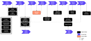
Figure 1: System Design – AUTOSAR Classic
B. AUTOSAR Adaptive System Design Process
AUTOSAR Adaptive provides a service-based platform where the functional and safety requirements are mapped to the functional architecture – see Figure 2.
As depicted in the diagram, the first step involves defining service interfaces and their deployment. Adaptive components are defined in the following step, and the network topology is created. Executable files are packaged and allocated to machines. Finally, service instances are deployed, and the system manifest (ARXML) is generated. This will allow flexible deployment, dynamic service discovery, and scalable execution, which are necessary features of SDV applications with centralized and high-performance computing platforms.
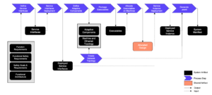
Figure 2: System Design – AUTOSAR Adaptive
III. Software Product lifecycle management: requirements and challenges
To ensure the integrity and reliability of these complex systems, a comprehensive approach to S-PLM is required, which combines applicable processes – e.g., cybersecurity, functional safety and ASPICE – in a single data-driven environment.
A. Cybersecurity (ISO/SAE 21434)
ISO/SAE 21434 is an international standard that defines cybersecurity requirements and processes for road-vehicle development, production, operation, and maintenance. The standard is organized into several layers, beginning with the organizational cybersecurity management layer, which defines cybersecurity governance, tool management, and organizational cybersecurity audit. It then defines project dependent cybersecurity management, covering activities such as cybersecurity planning, component reuse and the definition and assessment of the cybersecurity case. Recognizing the complexity of the automotive supply chain, the standard also regulates distributed and continual cybersecurity activities. Distributed activities include supplier capability, request for quotation (RFQ) processes and alignment of responsibilities, while continual cybersecurity activities include cybersecurity monitoring, vulnerability analysis and management. The final layer is TARA methodology where steps such as asset identification, threat scenario definition, attack path analysis, and risk treatment decisions are performed.
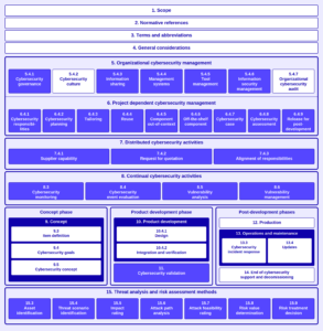
Figure 3: ISO/SAE 21434
To implement these standards effectively, organizations utilize a Cybersecurity Management System (CSMS) that spans the entire vehicle lifecycle, effectively merging development and operations into a continuous feedback loop. The first step is ‘Concept’ phase, where Threat Analysis and Risk Assessment (TARA) is performed, and cybersecurity goals are specified. The next step is ‘Development’ phase where cybersecurity requirements are defined from previous goals, followed by a ‘Testing and Validation’ phase. The post-production phase includes incident control and software update management systems (SUMS). New Common Vulnerabilities and Exposures (CVEs) and zero-day vulnerabilities are constantly monitored to ensure timely deployment of cybersecurity updates. This lifecycle-oriented approach integrates cybersecurity activities across development, production, and operation – see Figure 4.
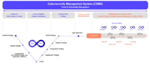
Figure 4: Cybersecurity Management System (CSMS)
An integrated V-model helps in combining design phase (vehicle design, system design, component development) with testing phase (that includes component testing, integration testing and vehicle testing) using continuous integration and continuous deployment (CI/CD) practices. Cybersecurity features and mitigations are continuously validated and deployed after the vehicle has been produced. Over-the-air (OTA) updates are also used to ensure that the vehicle remains within the scope of the regulations and operative effectiveness in case some new CVEs and security vulnerabilities are discovered.
B. Functional Safety (ISO 26262)
Functional Safety aims at vehicle safety, which can be guaranteed by reducing risks due to the malfunctioning behavior of E/E systems. To do this, Hazard Analysis and Risk Assessment (HARA) is used to determine potential hazards, with the assistance of systematic guideword and situation analysis to characterize the operational situations. Based on HARA, safety goals are established, and the scope is defined for creating a Functional Safety Concept (FSC) as well as a more detailed Technical Safety Concept (TSC), which clearly stipulate the required safety mechanisms in the form of safety requirements. The lifecycle has been designed to be robust using methods of deductive and inductive analysis, e.g., Fault Tree Analysis (FTA) and Failure Mode and Effects Analysis (FMEA). Finally, all results of test and verification work are summarized in the form of a safety case, which can be structured using Goal Structuring Notation (GSN) to present a logical argument that the system is safe to use.
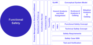
Figure 5: Functional Safety
The application of these principles is regulated by the ISO 26262 standard (Figure 6) that is based on a strict “V-Model” framework by taking into account the lifespan of a product. The workflow imposes traceability at different stages and layers:
- Concept Phase: This is the phase involving the definition of items (3-5), and hazard analysis (3-6) to determine the functional safety concept.
- Product Development: The safety requirements are broken down in a sequential manner into system (4-6), hardware (5-6), and software (6-6) requirements.
- Production and operation: Safety during production, operation and eventual decommissioning (7-5).
While the ISO 26262 standard establishes necessary theoretical framework for system safety, the proposed S-PLM platform provides a robust, practical implementation of these requirements. By maintaining rigorous end-to-end traceability across all development processes, the proposed S-PLM technique guarantees that critical safety goals are never overlooked amidst the complex iterations characteristic of SDV development.
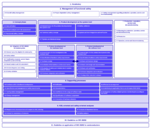
Figure 6: ISO 26262
C. ASPICE and Process Compliance
The automotive industry uses the Automotive SPICE (ASPICE) model to guarantee the quality and reproducibility of software. This framework divides engineering activities into logical process groupings to establish strict traceability and quality control. The main engineering activities are divided into the System Engineering Process Group (SYS), Software Engineering Process Group (SWE), and Hardware Engineering Process Group (HWE) as shown in Figure 7. These core activities are surrounded by the Supporting Processes (SUP), like quality assurance (SUP.1) and configuration management (SUP.8), which ensure that the engineering work is done properly and in a consistent manner throughout the entire project.
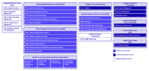
Figure 7: ASPICE – Process Reference Model
To address security gaps in SDVs, the framework incorporates the Automotive SPICE for Cybersecurity extension (Figure 8), effectively treating security not as an isolated silo but as a core engineering discipline. The update introduces a dedicated Cybersecurity Engineering Process Group (SEC), enforcing full traceability from SEC.1 (Cybersecurity Requirements Elicitation) through SEC.4 (Risk Treatment Validation). It also significantly impacts standard management and acquisition processes. For instance, the Management Process Group (MAN) now includes MAN.7 for cybersecurity risk management, enabling project managers to track security risks alongside traditional project risks. Similarly, the Acquisition Process Group (ACQ) is expanded with ACQ.2, ensuring that supplier selection depends on verified cybersecurity capabilities rather than cost alone.
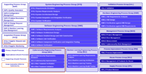
Figure 8: ASPICE + Cybersecurity – Process Reference Model
IV. Immobilizer Manager Case Study: Best Practices for a Multi-domain Data-driven Solution
In this section, a case study of an automotive immobilizer manager is presented to showcase practical implementation of the proposed S-PLM approach.
The immobilizer manager is an anti-theft system which protects the vehicle from an unauthorized start. The system architecture of the immobilizer manager is kept compliant with AUTOSAR specifications. It is based on a central SWC, ImobMgr. ImobMgr SWC receives input signals, including key identification and remote key validation via receiver ports (R-port) whereas its outputs signals include control requests that alarms and steering column locking via provider ports (P-port).
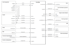
Figure 9: Immobilizer – System Design & Interfaces
A. Function Realization and Traceability
The solution offers a multi-domain, data-driven system design that supports traceability across logical and physical architectures. Design graph is used to visualize function realization, where function requirement (FR) blocks are mapped across electronic system architecture. The design graph can also be generated for mixed AUTOSAR architectures including Classic and Adaptive platforms, through Signal-to-Service (S2S) models.
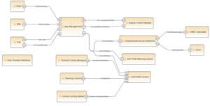
Figure 10: Design Graph – Function Realization
Requirements can be traced backward and forward easily. As shown in Figure 11, the system traces the “engine start/stop” function requirement directly back to the legal requirement “UNECE Regulation No. 155”. This ensures that the design requirement “key authentication before engine start” is not just a functional choice, but a legally justifiable compliance linked to international cybersecurity mandates.
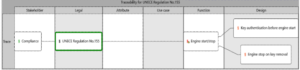
Figure 11: Requirement Traceability and Mapping
B. Cybersecurity and Safety Modeling
The case study demonstrates how the requirements of ISO/SAE 21434 and ISO 26262 are integrated to develop the solution model design. As part of the cybersecurity system model, Threat Analysis and Risk Assessment (TARA) is performed to identify relevant damage scenarios and their associated operational, safety, and financial impacts along with threat scenarios and attack paths.
TARA grid is used to add damage scenarios, threat scenarios, and attack paths to an asset. As illustrated in Figure 12, for the asset ImobECU/Cluster, a specific threat scenario ‘Compromised IMMO key ID’ is added with a residual risk level of 2. The associated attack path “make communication happen with a new key…” have ‘very low’ feasibility but ‘major’ financial and operational impact. Based on the assessment, it is assigned cybersecurity requirements ‘Secure Boot’ and ‘Secure Onboard Communication’ and links them directly to the ImobECU/Clustercomponent, ensuring that the mitigation measures are explicitly traceable to the identified threat.
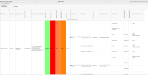
Figure 12: Security Grid
The security graph visually represents the relationship between assets, damage scenarios, threat scenarios, attack paths, and requirements. In parallel, functional safety activities are performed using Hazard Analysis and Risk Assessment (HARA), Fault Tree Analysis (FTA), and Failure Mode and Effects Analysis (FMEA). The graph in Figure 13 provides traceability among assets, damage scenarios, threat scenarios, attack paths, and design functions.
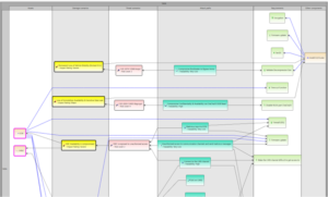
Figure 13: Security Graph

For functional safety modeling, HARA grid is used to trace hazards from identification to safety goal assignment. As shown in Figure 14, for hazardous event HEV-8 ‘A thief clones the key fob and starts the engine’, the event is given severity level S0, exposure of E2 and controllability of C2. From these parameters, it is assigned Automotive Safety Integrity Level (ASIL) QM. After assigning the ASIL level, the event is mapped to a Safety Goal 1 (SG-1) ‘The Immobilizer must prevent unauthorized Engine start’. This safety goal is then assigned ASIL-B determined by the worst-case event linked to this goal, requiring that the software development for this function adheres to stricter safety requirements than those implied by the individual event assessment alone.
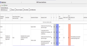
Figure 15: HARA Grid
The safety graph visually represents the relationships between safety requirements, hazards, hazardous events, and safety goals, including their associated ASIL levels.
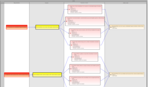
Figure 16: Safety Graph
As illustrated in Figure 16, the safety graph provides traceability from identified failure modes to defined safe states.

C. ASPICE Process Compliance
To enable compliance with ASPICE, the S-PLM solution additionally enables the traceability of engineering tasks and products to ASPICE process reference models.
As shown in Figure 18, internal process steps are mapped to relevant ASPICE 3.1 process standards. For example, process step “design requirements” is associated with SYS.2 (System Requirements Analysis), while “defining the scope of software qualification tests” is linked with SWE.6 (Software Qualification Test).
This process creates evidence for compliance on an ongoing basis throughout the entire engineering process.
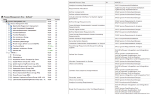
Figure 18: ASPICE Process Management
V. Summary and Conclusion
SDVs demand a complete overhaul of the current fragmented tool chains to single data-driven engineering platform. The case study illustrates how an effective S-PLM approach can manage system design, implementation, and verification in different domains of SDVs.
Organizations can uphold traceability, control the changes effectively and enable continuous compliance throughout the vehicle lifecycle by integrating functional safety, cybersecurity, and ASPICE compliance into a single product model. An open-standards-based approach that is built on top of AUTOSAR and uses model-based systems engineering (MBSE) best practices provides a basis for developing SDVs that are scalable and adaptable.
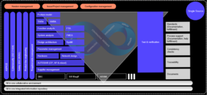
Figure 19: Pieces to be successful in SDV
VI. References
[1] AUTOSAR, Automotive Open System Architecture. https://www.autosar.org
[2] ISO/SAE, ISO/SAE 21434: Road Vehicles – Cybersecurity Engineering. Geneva, Switzerland: International Organization for Standardization, 2021.
[3] ISO, ISO 26262: Road Vehicles – Functional Safety. Geneva, Switzerland: International Organization for Standardization, 2018.
[4] VDA QMC Working Group, Automotive SPICE Process Assessment Model. Germany.